Everything you need is in one convenient list. Click above to start building your Zeus Supercomputer today.
Complete Parts List
| # | Component | Model | Price |
|---|---|---|---|
| 1 | CPU | AMD Ryzen 9 9950X 16-Core, 32-Thread | $519.00 |
| 2 | GPU | PNY NVIDIA GeForce RTX 5090 OC Triple Fan | $4,199.99 |
| 3 | Motherboard | ASRock AMD X870E Taichi | $329.99 |
| 4 | RAM | Corsair Vengeance DDR5 128GB (2x64GB) | ~$350.00 |
| 5 | SSD | Samsung 990 EVO Plus 4TB PCIe Gen 4x4 | $613.15 |
| 6 | HDD | Seagate IronWolf 12TB | $369.99 |
| 7 | PSU | be quiet! Pure Power 12 M 1200W Modular | $179.90 |
| 8 | CPU Cooler | be quiet! Silent Loop 3 360mm AIO | $116.91 |
| 9 | Case | Corsair 7000D Airflow Full-Tower ATX | $269.99 |
| 10 | Thermal Paste | Arctic MX-6 (4g) | $5.99 |
| 11 | UPS | APC Back-UPS Pro 1000VA | $183.99 |
| 12 | RGB Lighting | Speclux PC RGB Strip 3pcs 5050 Magnetic | $22.99 |
| 13 | Network Card | BZIZU 10Gb PCIe NIC Network Card | $35.98 |
| TOTAL BUILD COST: | $7,197.88 | ||
Tools & Supplies Needed
Before you begin, gather these essential tools and supplies:
- Phillips Head Screwdriver — Magnetic tip preferred for easier screw handling
- Anti-Static Wrist Strap — Critical for protecting sensitive components
- Cable Ties / Velcro Straps — For cable management (20-30 pieces recommended)
- Scissors or Wire Cutters — For trimming cable ties
- Flashlight or Headlamp — For seeing inside the case clearly
- Tweezers — Helpful for dropped screws and small connectors
- Isopropyl Alcohol (90%+) — For cleaning surfaces before thermal paste application
- Lint-Free Cloth or Coffee Filters — For cleaning CPU/cooler contact surfaces
- GPU Support Bracket — Highly recommended for the RTX 5090 (extremely heavy card)
Safety First: Anti-Static Precautions
Follow these anti-static protocols religiously:
- Wear an anti-static wrist strap clipped to a grounded metal surface (case frame, grounded outlet screw)
- Work on a non-carpeted surface — hardwood, tile, or concrete floors are ideal
- Touch a grounded metal object before handling components if not wearing a wrist strap
- Never work in socks on carpet — this is a recipe for static discharge
- Keep components in anti-static bags until immediately before installation
- Avoid wearing synthetic fabrics like fleece or polyester while building
- Handle PCBs by the edges only — never touch gold contacts, chips, or circuitry
Step-by-Step Assembly Instructions
Follow these steps in order. Do not skip ahead. Each step builds on the previous one.
Prepare Your Workspace
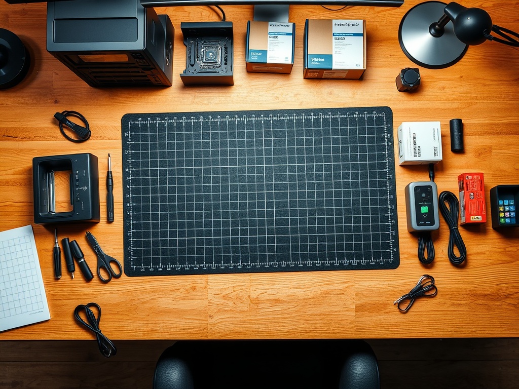
Parts needed: None (preparation step)
Estimated time: 10 minutes
- Clear a large, flat surface — You'll need at least 4 feet of workspace for the case and parts
- Ensure good lighting — Overhead lights plus a desk lamp or flashlight for case interior
- Ground yourself — Put on your anti-static wrist strap and clip it to the case frame or grounded outlet screw
- Unbox all components carefully — Keep anti-static bags, manuals, and accessory boxes organized
- Verify all parts are present — Check against the parts list above and your order confirmations
- Read motherboard manual — The ASRock X870E Taichi manual contains critical diagrams for headers, slots, and connectors
Prepare the Case (Corsair 7000D Airflow)
Parts needed: Corsair 7000D Airflow Case
Estimated time: 15 minutes
- Remove the case from its box — Carefully lift it out and place on your workspace
- Remove the tempered glass side panels — Unlock the thumb screws at the rear and slide panels backward to release
- Remove the PSU cover/shroud — This usually has 2-4 screws securing it (check manual for exact location)
- Identify all pre-installed fans — The 7000D Airflow comes with 3x 140mm fans (2 front intake, 1 rear exhaust)
- Locate the motherboard standoffs — These brass spacers should already be installed for ATX form factor. Count them (should be 9 for ATX)
- Remove the rear I/O shield — Pop out the generic metal plate from the back of the case. You'll replace this with the X870E Taichi's custom I/O shield
- Check for included accessories — Find the screw box, cable ties, and any additional mounting hardware
Install the CPU (AMD Ryzen 9 9950X)
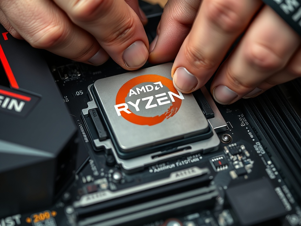
Parts needed: AMD Ryzen 9 9950X, ASRock X870E Taichi Motherboard
Estimated time: 10 minutes
CRITICAL: This is the most delicate step. The CPU pins are extremely fragile and can bend if handled incorrectly. Take your time.
- Place the motherboard on a non-conductive surface — Use the motherboard box or an anti-static mat
- Locate the AM5 CPU socket — It's the large square socket in the center-top area of the motherboard
- Unlock the CPU socket lever — Push the metal retention arm down and out to the side, then lift it to 90 degrees
- Remove the protective socket cover — Gently lift the black plastic cover off. Save this cover in case you need to RMA the motherboard
- Remove the CPU from its packaging — Hold it by the edges only. Never touch the gold contact pads on the bottom
- Locate the golden triangle alignment markers — Both the CPU corner and socket have a small gold/etched triangle. These MUST align
- Align the CPU over the socket — Match the golden triangles. The CPU should hover just above the socket pins
- Drop the CPU straight down — Do NOT slide or wiggle it. It should fall into place with zero resistance. If you feel ANY resistance, STOP and check alignment
- Verify the CPU is fully seated — Look at all four sides. The CPU should sit flush and even with the socket frame
- Lower the retention arm — Gently push the metal arm back down. It will require moderate force to lock. You'll hear a click
- Secure the retention clip — Hook the arm back under the retention tab
Apply Thermal Paste (Arctic MX-6)

Parts needed: Arctic MX-6 Thermal Paste, Isopropyl Alcohol (90%+), Lint-Free Cloth
Estimated time: 5 minutes
Proper thermal paste application is critical for CPU cooling performance. Too much paste causes overflow and mess. Too little causes hotspots and thermal throttling.
- Clean the CPU heat spreader — Use isopropyl alcohol on a lint-free cloth to wipe the CPU surface. Let it dry completely (30 seconds)
- Shake the Arctic MX-6 syringe — Mix the compound by shaking for 10 seconds
- Apply a small rice grain-sized dot — Place a single dot in the CENTER of the CPU heat spreader. For the Ryzen 9 9950X, a dot roughly 4-5mm in diameter is perfect
- Do NOT spread the paste manually — Let the cooler mounting pressure spread it evenly. Manual spreading traps air bubbles and reduces thermal performance
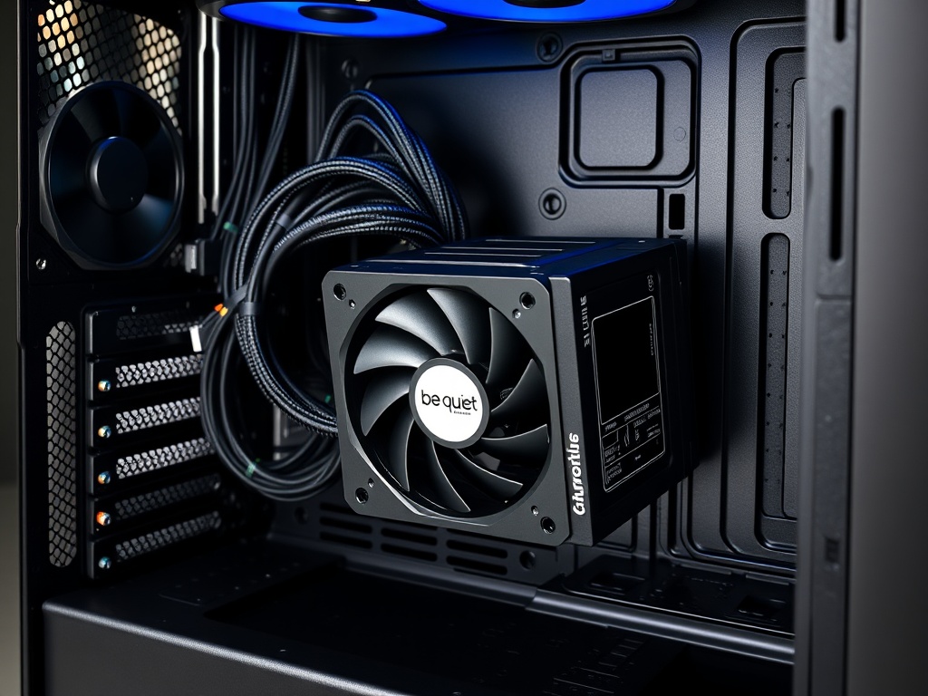
Install AIO Cooler (be quiet! Silent Loop 3 360mm)
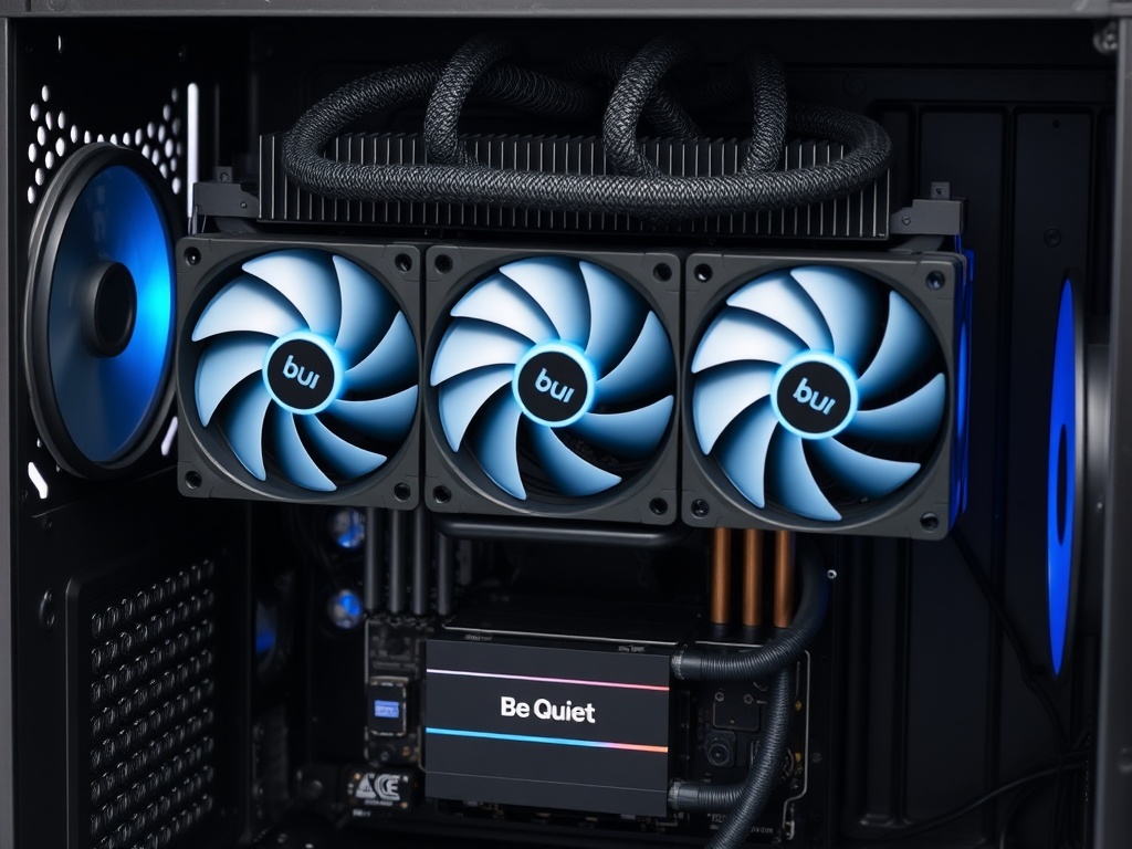
Parts needed: be quiet! Silent Loop 3 360mm AIO, AM5 mounting bracket (included), screws
Estimated time: 25 minutes
The Silent Loop 3 is a 360mm All-In-One liquid cooler. We'll mount the pump/block to the CPU and the radiator to the case's top panel.
- Remove the default AM4 brackets from the motherboard — Unscrew the four plastic retention clips around the CPU socket. These are for AM4; we need AM5 mounting
- Install the AM5 backplate — Flip the motherboard over. Align the metal AM5 backplate (from the Silent Loop 3 box) with the four holes around the socket. The backplate should sit flush against the back of the motherboard
- Thread the standoffs through from the front — From the motherboard front, screw the four metal standoffs through the mounting holes and into the backplate. Tighten until snug but not over-torqued
- Apply thermal paste (already done in Step 4) — Verify the paste dot is still centered and undisturbed
- Remove the protective film from the pump cold plate — Peel off the clear plastic sticker from the bottom of the pump block. Do NOT touch the copper surface
- Position the pump block over the CPU — Align the four corners of the pump bracket with the standoffs. The be quiet! logo should be upright (readable)
- Hand-tighten the four thumb screws — Screw in a cross pattern (top-left → bottom-right → top-right → bottom-left). Tighten each screw 2-3 turns at a time to ensure even pressure. Tighten until firm, but don't over-torque. You should feel solid resistance but not need excessive force
- Connect the pump power cable — Find the 3-pin or 4-pin cable from the pump. Plug it into the CPU_FAN header on the motherboard (consult the X870E Taichi manual for location; it's usually near the CPU socket)
- Connect the AIO RGB/control cable (if applicable) — The Silent Loop 3 may have a USB or RGB header cable. Consult the cooler manual and connect to the appropriate motherboard headers
- Prepare the radiator mounting — The Corsair 7000D Airflow supports top-mounted 360mm radiators. You'll mount the radiator with fans in a push or pull configuration
- Mount fans to radiator — Attach the three 120mm fans (included with the AIO) to the radiator using long radiator screws. Orient fans so they pull air UP through the radiator and exhaust out the top of the case
- Position radiator inside the case top — Align the radiator/fan assembly with the top mounting holes. You may need to temporarily remove the top panel of the case for easier access
- Secure the radiator to the case — Use the included case screws to mount the radiator through the top panel. Ensure all tubes have clearance and aren't kinked
- Connect fan power cables — Daisy-chain the three 120mm fans or connect them individually to motherboard fan headers (CPU_FAN1, CPU_FAN2, SYS_FAN1, etc.)
- Verify tube routing — Ensure the AIO tubes aren't kinked, crushed, or putting strain on the pump. The tubes should have a gentle curve from the pump to the radiator
Install RAM (Corsair Vengeance DDR5 128GB)
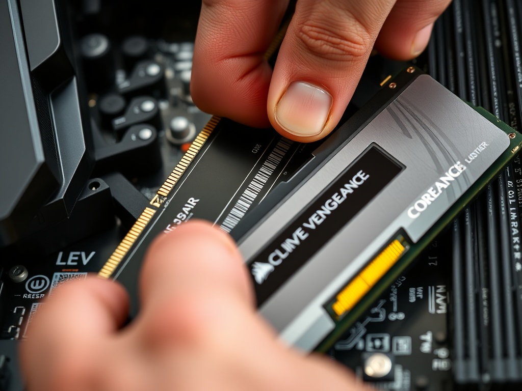
Parts needed: Corsair Vengeance DDR5 128GB Kit (2x 64GB sticks)
Estimated time: 5 minutes
DDR5 memory must be installed in the correct slots for optimal dual-channel performance.
- Locate the DDR5 DIMM slots — The X870E Taichi has four DDR5 slots to the right of the CPU socket. They're labeled A1, A2, B1, B2 (or similar; check your motherboard manual)
- Identify the correct slots for 2-DIMM configuration — For dual-channel with 2 sticks, you MUST use slots A2 and B2 (the 2nd and 4th slots from the CPU). Consult your motherboard manual to confirm slot labels
- Open the retention clips — Push down the plastic clips at the ends of the A2 and B2 slots until they're fully open (90 degrees)
- Remove RAM from anti-static packaging — Handle sticks by the edges. Don't touch the gold contacts
- Align the notch — DDR5 has an off-center notch that prevents incorrect insertion. Align this notch with the key in the DIMM slot
- Insert the first stick into slot A2 — Hold the stick vertically above the slot. Press down firmly and evenly on both ends. The stick should slide in smoothly. You'll hear a click when the retention clips snap into place
- Insert the second stick into slot B2 — Repeat the process. Both sticks should sit flush and even in their slots
- Verify installation — The retention clips should be fully closed and locked. The RAM sticks should not wobble or sit unevenly
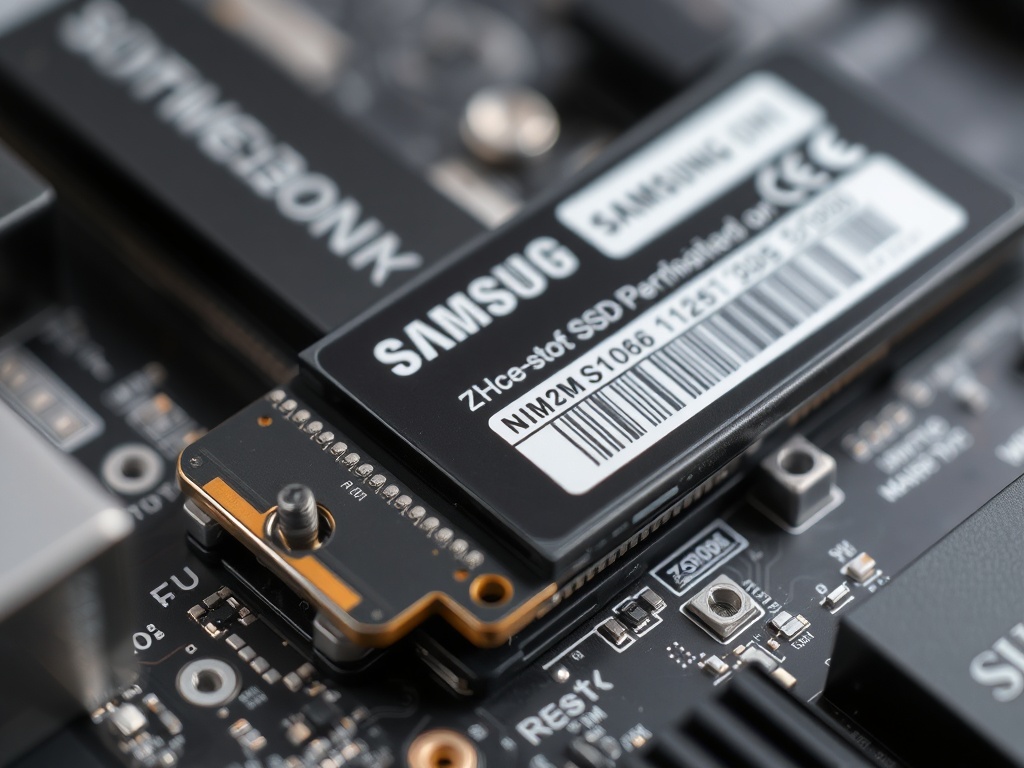
Install M.2 SSD (Samsung 990 EVO Plus 4TB)
Parts needed: Samsung 990 EVO Plus 4TB, M.2 mounting screw (included with motherboard)
Estimated time: 8 minutes
The Samsung 990 EVO Plus is a PCIe Gen 4x4 NVMe SSD in M.2 2280 form factor. The X870E Taichi has multiple M.2 slots with integrated heatsinks.
- Locate the primary M.2 slot — The X870E Taichi typically has 3-5 M.2 slots. Use the M.2_1 slot (usually labeled as the primary PCIe Gen 5 or Gen 4 slot closest to the CPU). Consult your motherboard manual for exact location
- Remove the M.2 heatsink cover — The primary slot has a metal heatsink cover secured with 1-2 screws. Remove the screws and lift the heatsink straight up. Save the thermal pad that's stuck to the heatsink
- Identify the M.2 mounting screw hole — For a 2280 drive (80mm), find the screw hole labeled "2280" on the motherboard. There should be a small standoff or threaded hole
- Remove the Samsung SSD from packaging — Handle by the edges. Don't touch the gold connector pins or controller chips
- Insert the SSD at a 30-degree angle — Align the notch on the SSD with the key in the M.2 slot. Gently slide it into the connector at an angle. The SSD will stick up at about 30 degrees
- Press the SSD down flat — Gently push the opposite end of the SSD down until it's parallel with the motherboard. It should align with the mounting hole
- Secure with the M.2 mounting screw — Use the tiny screw included with your motherboard to secure the SSD. Tighten gently until snug. Do NOT overtighten — M.2 screws strip very easily
- Reattach the M.2 heatsink — Place the heatsink back over the SSD (thermal pad should contact the SSD controller). Secure with the original screws
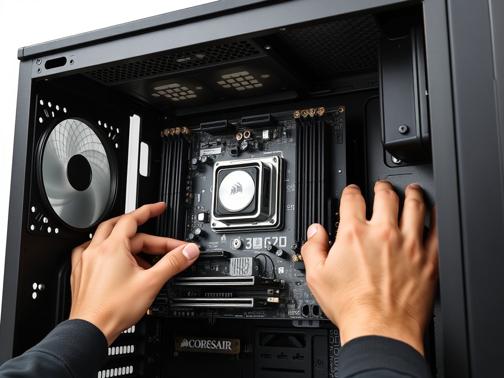
Mount Motherboard into Case
Parts needed: Motherboard (with CPU, RAM, cooler, M.2 installed), Corsair 7000D case, motherboard I/O shield, motherboard screws
Estimated time: 15 minutes
- Install the I/O shield — The X870E Taichi includes a custom I/O shield (the metal plate that fits in the rear case opening). Pop it into place from the INSIDE of the case. It should snap in with the ports facing outward. Ensure all four corners are fully seated
- Verify motherboard standoffs — The Corsair 7000D should have ATX standoffs pre-installed. Count them (9 total for ATX). They're the small brass hex posts. If any are missing, install them using the standoff installation tool (looks like a hex key with a threaded hole)
- Carefully lift the motherboard — Support it from underneath with both hands. Be mindful of the AIO pump block and tubes
- Align the I/O ports with the I/O shield — Lower the motherboard toward the case, lining up the rear USB/audio/Ethernet ports with the I/O shield cutouts. This requires patience; wiggle gently until all ports are aligned
- Check that all standoff holes align — Once the I/O is seated, verify that the motherboard screw holes line up with the standoffs underneath. You should see brass standoffs through each hole
- Install the motherboard screws — Use the included motherboard screws (they're typically silver with a rounded head). Start by hand-threading one screw in the center, then one in each corner. Tighten in a star pattern to distribute pressure evenly. Tighten until snug but not over-torqued
- Verify the board is secure — Gently press on the motherboard. It should not flex or wobble
Install PSU (be quiet! Pure Power 12 M 1200W)
Parts needed: be quiet! Pure Power 12 M 1200W Modular PSU, PSU mounting screws (included with case), modular cables
Estimated time: 20 minutes
The be quiet! Pure Power 12 M is a modular PSU, meaning you only connect the cables you need. This reduces clutter and improves airflow.
- Identify the PSU mounting area — In the Corsair 7000D, the PSU mounts in the bottom rear of the case, typically with the fan facing DOWN (toward the bottom ventilation holes)
- Prepare the PSU — Remove it from the box. The fan should face down for intake from the bottom case vent. The rear power connector and switch should face the back of the case
- Slide the PSU into the case — Insert it from inside the case, pushing it toward the rear until the screw holes align with the case mounting holes. The rear I/O (power plug and switch) should be flush with the case rear panel
- Secure the PSU with four screws — Use the four PSU screws included with the case. Tighten from the back of the case, securing the PSU firmly
- Identify required cables — For this build, you'll need:
- 24-pin ATX motherboard power (main power)
- 8-pin EPS CPU power (usually labeled "CPU" or "EPS12V")
- 16-pin 12VHPWR GPU power for the RTX 5090 (may be labeled "PCIe 5.0" or come with an adapter from multiple 8-pin PCIe)
- SATA power cables for the 12TB HDD
- (Optional) Peripheral/Molex cables for RGB strips or accessories
- Connect modular cables to the PSU — Each cable plugs into labeled ports on the PSU. The connectors are keyed to prevent incorrect insertion:
- 24-pin ATX → "MB" or "Motherboard" port on PSU
- 8-pin EPS → "CPU" port on PSU
- 16-pin 12VHPWR (or 8-pin PCIe adapters) → "PCIe" or "VGA" ports on PSU
- SATA → "SATA" or "Peripheral" ports on PSU
- Route cables through the case — Use the cable management grommets and routing holes in the Corsair 7000D. Route cables behind the motherboard tray (we'll connect them in the next step)
Cable Management & Power Connections

Parts needed: All PSU cables (from Step 9), cable ties, motherboard manual
Estimated time: 25 minutes
Now we'll connect all power cables to the motherboard and components. This step requires careful attention to connector types and locations.
- Connect the 24-pin ATX power — Locate the large 24-pin connector on the right side of the motherboard. Route the cable from the PSU through the nearest cable management grommet. Align the clip and press firmly until it clicks into place
- Connect the 8-pin EPS CPU power — Locate the 8-pin (or 4+4 pin) CPU power connector at the TOP LEFT of the motherboard, near the I/O shield. This powers the CPU. Route the cable behind the motherboard tray and through the top-left grommet. Press firmly until it clicks
- Connect front panel headers — These are the small connectors for power button, reset button, HDD LED, and power LED. They're located at the BOTTOM RIGHT of the motherboard (consult your manual). The pins are labeled, but they're tiny:
- PWR_SW (Power Switch) — Usually a 2-pin connector. Polarity doesn't matter
- RESET_SW (Reset Switch) — 2-pin, polarity doesn't matter
- HDD_LED (Hard Drive Activity LED) — 2-pin, polarity DOES matter (+ and -)
- PWR_LED (Power LED) — 2-pin or 3-pin, polarity matters
- Connect front panel USB headers — Locate the USB 2.0 header (9-pin) and USB 3.0/3.2 header (19-pin or Type-C) on the motherboard. Connect the corresponding cables from the case's front panel I/O. These connectors are keyed and only fit one way
- Connect front panel audio header — Find the HD Audio header (usually labeled "JAUD1" or "AAFP") on the bottom edge of the motherboard. Connect the case's front panel audio cable
- Connect case fans to fan headers — The Corsair 7000D comes with 3x 140mm fans. Plus, you have 3x 120mm fans on the AIO radiator. Connect these to motherboard fan headers:
- AIO fans → CPU_FAN or SYS_FAN headers
- Case fans → SYS_FAN headers
- Cable management — Use cable ties or Velcro straps to bundle cables neatly behind the motherboard tray. Route cables along the built-in channels in the case. Keep cables away from fan blades and ensure they don't obstruct airflow
- Verify all connections — Double-check:
- 24-pin ATX power → Motherboard (clicked in)
- 8-pin EPS → CPU power (clicked in)
- Front panel headers → All connected correctly
- USB headers → Front panel USB
- Audio header → Front panel audio
- Fan headers → All fans connected
- AIO pump → CPU_FAN header
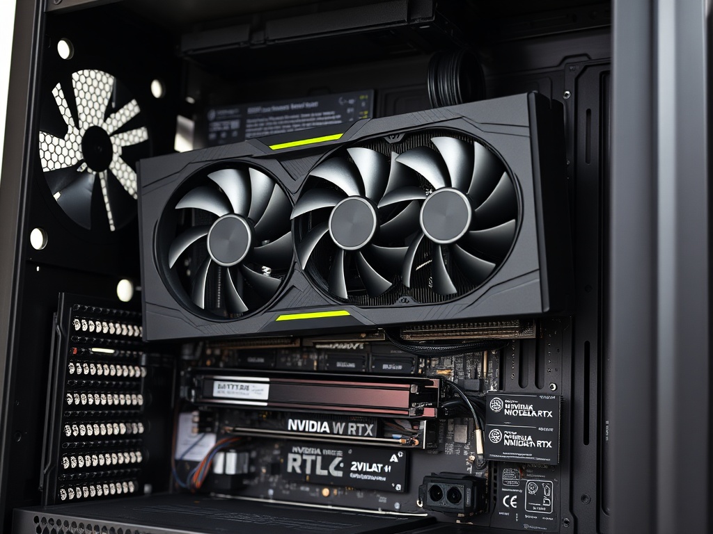
Install GPU (PNY NVIDIA RTX 5090 OC)
Parts needed: PNY RTX 5090, 16-pin 12VHPWR power cable (or 3x 8-pin to 16-pin adapter), GPU support bracket (highly recommended)
Estimated time: 15 minutes
IMPORTANT: The RTX 5090 is an EXTREMELY heavy GPU (over 5 lbs / 2.3 kg). You MUST use a GPU support bracket or vertical mount to prevent PCIe slot damage over time.
- Identify the primary PCIe x16 slot — This is the TOP full-length PCIe slot on the motherboard, usually labeled "PCIE1" or "PCIE_1" and reinforced with metal. It's directly connected to the CPU for maximum bandwidth
- Remove the rear PCIe slot covers — The RTX 5090 is a 3-slot or 3.5-slot card. Remove 3-4 slot covers from the rear of the case (the vertical metal plates). Unscrew them and set aside
- Remove the GPU from its anti-static bag — Handle by the metal bracket and backplate edges. Avoid touching the gold PCIe connector pins or PCB components
- Align the GPU with the PCIe slot — Hold the card horizontally above the slot. The gold connector edge should align with the PCIe slot, and the metal I/O bracket should align with the rear case opening
- Press the GPU into the slot — Apply firm, even pressure. The card should slide smoothly into the slot. You'll hear a click when the retention clip locks. The GPU should sit level and the I/O ports should be flush with the case rear
- Secure the GPU bracket to the case — Use 2-3 screws to attach the GPU's metal I/O bracket to the case rear panel (where you removed the slot covers)
- Install a GPU support bracket — Because the RTX 5090 is so heavy, install a vertical support bracket under the far end of the card. This prevents GPU sag and PCIe slot damage. Support brackets typically rest on the bottom of the case and have an adjustable arm that props up the GPU. Adjust until the GPU is perfectly level
- Connect the 16-pin 12VHPWR power cable — Locate the 16-pin power connector on the TOP EDGE of the GPU (near the rear I/O bracket). Route the 16-pin cable from the PSU and connect it to the GPU. Press firmly until it clicks. Ensure the cable is fully inserted — a loose connection can cause the connector to melt under high power draw
- Verify clearance — Check that the GPU fans have clearance from the side panel and other components. The card should not be touching or rubbing against anything
Install HDD (Seagate IronWolf 12TB)
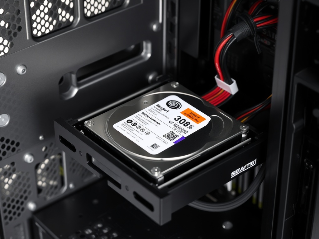
Parts needed: Seagate IronWolf 12TB 3.5" HDD, HDD mounting screws, SATA power cable, SATA data cable
Estimated time: 10 minutes
- Locate the 3.5" drive bays — The Corsair 7000D has dedicated 3.5" HDD cages, usually in the front or bottom of the case. Some cases use tool-less drive trays
- Remove a drive tray — If your case uses tool-less trays, press the release tab and slide the tray out. If screw-mounted, skip this step
- Mount the HDD to the tray — Align the screw holes on the sides of the HDD with the tray holes. Secure with 4 screws (2 per side). If mounting directly in the cage, slide the HDD into the bay and secure with screws from the side
- Insert the tray back into the case — Slide it in until it clicks or locks into place
- Connect the SATA power cable — Route a SATA power cable from the PSU to the HDD. The connector is L-shaped and keyed. It only fits one way. Press gently until it's fully seated
- Connect the SATA data cable — Plug a SATA data cable (included with your motherboard) into the HDD. The other end connects to a SATA port on the motherboard (usually labeled SATA1, SATA2, etc., located along the bottom edge). SATA cables are keyed and only fit one way
Install 10Gb NIC (BZIZU PCIe Card)
Parts needed: BZIZU 10Gb PCIe NIC Network Card
Estimated time: 5 minutes
- Identify an available PCIe x4 or x8 slot — The 10Gb NIC requires at least a PCIe x4 slot. Use the second or third full-length PCIe slot (below the GPU). Consult your motherboard manual to avoid disabling M.2 slots (some slots share bandwidth)
- Remove the corresponding rear slot cover — Unscrew and remove the metal slot cover for the chosen PCIe slot
- Insert the NIC into the PCIe slot — Align the card's gold connector with the slot. Press down firmly until the retention clip clicks. The card should sit flush and level
- Secure the NIC bracket to the case — Use a screw to attach the NIC's metal I/O bracket to the rear case panel
Install RGB Strips (Speclux)
Parts needed: Speclux PC RGB Strip 3pcs, RGB controller (included), SATA power or Molex adapter
Estimated time: 10 minutes
- Plan your RGB strip placement — Common locations include: top edge near the radiator, bottom edge near the PSU shroud, or along the front panel edge. The strips are magnetic, so they'll stick to the case's metal frame
- Peel the adhesive backing — Remove the protective film from the adhesive side of each strip
- Attach the strips to the case — Press firmly along the entire length. The magnetic backing helps hold them in place on metal surfaces
- Connect strips to the RGB controller — The Speclux kit includes a controller box. Connect all three strips to the controller using the included connectors
- Power the RGB controller — Connect the controller to a SATA power cable from the PSU, or use a Molex adapter if provided
- Route the controller cable — Some RGB kits include a remote control or button. Route the controller wire to an accessible location (e.g., near the front I/O or outside the case)
- (Optional) Connect to motherboard RGB header — If your strips support motherboard RGB control (3-pin 5V ARGB or 4-pin 12V RGB), you can connect them to the motherboard for software control instead of the standalone controller
First Boot & BIOS Setup
Parts needed: Monitor, keyboard, HDMI/DisplayPort cable, power cable for PSU
Estimated time: 20 minutes
This is the moment of truth. Before closing up the case, we'll power on the system and configure the BIOS.
- Triple-check all connections — Before powering on, verify:
- 24-pin ATX power → Motherboard
- 8-pin EPS → CPU power
- 16-pin 12VHPWR → GPU (fully clicked in)
- All fans → Motherboard headers
- Front panel power button → Correct header pins
- Monitor cable → GPU (NOT motherboard — Ryzen 9 9950X has no integrated graphics)
- Connect the PSU power cable — Plug the power cable into the PSU rear I/O and a wall outlet
- Flip the PSU power switch to ON — The switch on the back of the PSU should be in the "I" (on) position. You may see motherboard LEDs light up (this is normal)
- Press the case power button — If wired correctly, the system should power on. You'll hear fans spin up and see the GPU fans start. The motherboard may display a POST code on a debug LED or screen
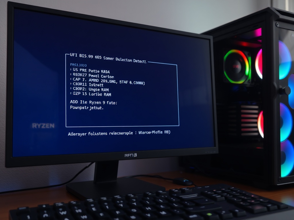
- Enter the BIOS — Immediately press the Delete or F2 key repeatedly as the system boots. This enters the UEFI BIOS setup. (The exact key varies by motherboard; watch the screen for the prompt)
- Verify CPU and RAM detection — In the BIOS main screen, check:
- CPU: Should read "AMD Ryzen 9 9950X" with correct core count (16 cores, 32 threads)
- RAM: Should show 128GB total capacity
- RAM Speed: Will likely show 4800 MT/s or 5200 MT/s (base JEDEC speed). This is normal; we'll enable XMP/EXPO next
- Enable XMP/EXPO memory profile — Navigate to the "OC Tweaker" or "Overclocking" section in the BIOS. Look for "XMP" or "EXPO" settings. Enable the profile to run your RAM at its rated speed (likely 5600 MT/s or higher). Save and apply
- Set boot priority — Go to the "Boot" section. Set the Samsung 990 EVO Plus 4TB M.2 SSD as the first boot device. This ensures the system boots from your OS drive (once you install an operating system)
- Check fan speeds and temperatures — Navigate to the hardware monitor or H/W Monitor section. Verify:
- CPU temperature is reasonable (30-45°C idle with AIO)
- All fans are detected and spinning (case fans, AIO fans, AIO pump)
- Enable Resizable BAR (ReBAR) — In the BIOS, find "Above 4G Decoding" and "Resizable BAR Support" settings (usually under "PCI Subsystem Settings" or "Advanced"). Enable both. This allows the CPU to access the full GPU VRAM, improving performance in modern games and AI workloads
- Save and exit — Press F10 (or the prompted key) to save all changes and exit the BIOS. The system will reboot
- Troubleshoot if it doesn't POST — If the system doesn't power on or display anything:
- Check the 24-pin and 8-pin EPS power connections (reseat them)
- Verify RAM is clicked into the correct slots (A2 + B2)
- Ensure monitor is plugged into the GPU, not the motherboard
- Check motherboard debug LEDs or POST code display for error codes
- Reseat the GPU (remove and reinstall)
Connect UPS (APC Back-UPS Pro 1000VA)
Parts needed: APC Back-UPS Pro 1000VA, power cable, USB cable (for monitoring)
Estimated time: 10 minutes
A UPS (Uninterruptible Power Supply) protects your expensive hardware from power outages, surges, and brownouts. The APC Back-UPS Pro 1000VA can keep your system running for 10-20 minutes during an outage, giving you time to save work and shut down safely.
- Unbox and position the UPS — Place the UPS on the floor near your desk or under your desk. It's heavy and should sit on a flat, stable surface with ventilation
- Charge the UPS battery — Before connecting your PC, plug the UPS into a wall outlet and let it charge for 8-12 hours (or per manufacturer instructions). Most UPS units ship with partially charged batteries
- Connect the PC power cable to the UPS — Unplug your PC's PSU from the wall outlet. Plug it into one of the UPS's battery backup + surge protection outlets (NOT the surge-only outlets). These are usually labeled on the UPS rear panel
- Connect monitor and peripherals — Plug your monitor, router, or other critical devices into the remaining battery backup outlets. Avoid connecting high-draw devices like printers or speakers to battery backup outlets (use surge-only outlets for those)
- Connect the USB monitoring cable (optional) — The APC Back-UPS Pro includes a USB cable for connecting to your PC. Plug it into a USB port on your motherboard. This allows UPS monitoring software to communicate with the UPS, providing battery status, estimated runtime, and automatic shutdown during extended outages
- Install APC PowerChute software (optional) — Download the APC PowerChute software from the APC website. This software monitors the UPS and can automatically save your work and shut down the PC gracefully if the battery is about to die during an outage
- Test the UPS — With the PC plugged into the UPS and the UPS plugged into the wall, turn on the PC. While the PC is running, unplug the UPS from the wall outlet to simulate a power outage. The UPS should switch to battery power instantly (you'll hear a beep and see the UPS LED change). The PC should continue running without interruption. Plug the UPS back in after 10-20 seconds to end the test
Completed Build Summary
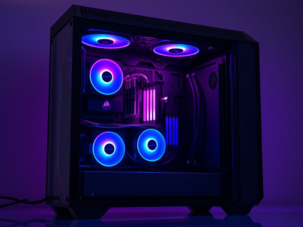
Congratulations! You've successfully assembled the Zeus Supercomputer — a top-tier workstation capable of:
- High-end gaming at 4K/8K resolution with maxed-out settings (RTX 5090)
- AI model training and inference (128GB RAM + 24GB VRAM)
- Video editing and 3D rendering (16-core Ryzen 9 9950X)
- Massive local storage (4TB NVMe SSD + 12TB HDD)
- High-speed networking (10Gb NIC for LAN transfers or NAS access)
- Content creation (live streaming, recording, multi-tasking)
Your build is future-proof and expandable. You can add more M.2 SSDs, upgrade to 256GB RAM, or even add a second GPU for specific workloads.
Total Cost Breakdown
| Category | Cost |
|---|---|
| CPU (Ryzen 9 9950X) | $519.00 |
| GPU (RTX 5090) | $4,199.99 |
| Motherboard (X870E Taichi) | $329.99 |
| RAM (128GB DDR5) | $350.00 |
| Storage (4TB SSD + 12TB HDD) | $983.14 |
| PSU (1200W) | $179.90 |
| Cooling (360mm AIO) | $116.91 |
| Case (Corsair 7000D) | $269.99 |
| Accessories (UPS, NIC, RGB, thermal paste) | $248.95 |
| TOTAL | $7,197.88 |
Price reflects current market rates. Check the Amazon Storefront for live pricing and availability.
Troubleshooting Quick Reference
| Issue | Solution |
|---|---|
| No display output | Verify monitor is plugged into GPU (not motherboard). Reseat GPU. Check GPU power cable is fully clicked in. |
| PC powers on but won't POST | Reseat RAM (ensure A2 + B2 slots). Check 24-pin ATX and 8-pin EPS connections. Clear CMOS (consult motherboard manual). |
| RAM not detected or wrong capacity | Reseat RAM firmly (push until both clips lock). Verify using A2 + B2 slots (not A1 + A2). |
| High CPU temps (70°C+ idle) | Check AIO pump is running (should see RPM in BIOS). Verify pump is connected to CPU_FAN header. Remount cooler with fresh thermal paste. |
| M.2 SSD not detected in BIOS | Reseat M.2 drive and secure screw. Check BIOS for disabled M.2 slots (some share bandwidth with PCIe slots). |
| GPU fans not spinning | Modern GPUs have zero-RPM fan modes (fans don't spin until ~55-60°C). This is normal. Test under load to verify fans work. |
| Power button does nothing | Check front panel header connections (especially PWR_SW). Verify PSU is switched on and plugged in. |
| System crashes after enabling XMP/EXPO | RAM instability. Reduce RAM speed in BIOS (e.g., 6000 MT/s → 5600 MT/s). Increase DRAM voltage slightly (+0.05V). |
| USB ports not working | Verify front panel USB headers are connected to correct motherboard headers (USB 2.0 and USB 3.0 are separate connectors). |
Post-Build Checklist
Complete these steps after your first successful boot:
Click above to access the complete parts list with live pricing and availability. Start building your Zeus Supercomputer today!
Need Help?
If you run into any issues during your build, consult your motherboard and component manuals. The ASRock X870E Taichi manual contains detailed diagrams for all headers and connectors. For additional troubleshooting, check online communities like r/buildapc on Reddit or the Linus Tech Tips forums.
Happy building!
— Lead Gen Jay